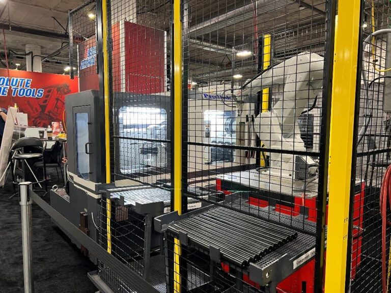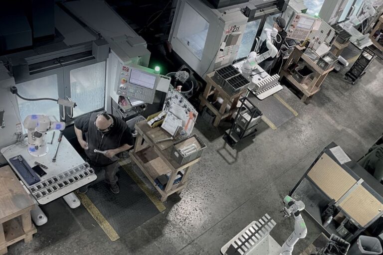
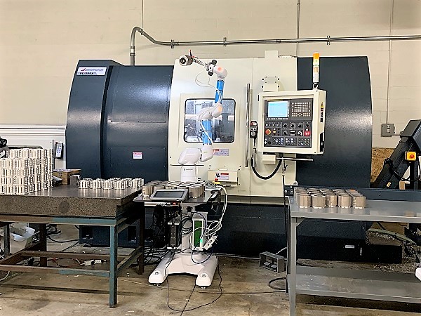
Successfully implementing a cobot in a CNC shop requires more than purchasing the unit and rolling it in front of the machine door. The cobot itself is one component of a larger automation cell that includes workspace planning, CNC integration, part staging, end-effector selection, and an ongoing maintenance routine. This guide covers all eight steps in sequence, from the first workspace assessment through go-live review.
Every year, manufacturers buy cobots that never make it into production. They arrive, get unpacked, moved to a corner of the shop, and sit there. The investment was sound. The machine was right for the application. The problem was implementation; nobody had a clear plan for how to get from “we bought a cobot” to “the cobot is running parts.”
This guide is for manufacturers who have decided a cobot is the right fit and are ready to plan the implementation. If you are still evaluating whether a cobot makes financial sense for your shop, start with How to Calculate ROI to Justify a Collaborative Robot first, then come back here when the math checks out.
Before You Start: A Cobot Is One Component of a Larger Cell
The cobot arm is the most visible piece of an automation cell, but it is rarely the most complex piece. Before the cobot arrives, a shop needs answers to at least six questions: Where will the cobot be positioned? How will parts be presented to it? What end-effector will it use? How will it communicate with the CNC machine? Who will integrate it? What does the maintenance routine look like?
Most implementation failures start here — not in the cobot itself, but in the planning around it. The OB7 from Productive Robotics is designed to make implementation as practical as possible: a no-programming teach platform, 7-axis reach, and broad CNC compatibility. But even the most user-friendly cobot on the market requires a cell to be built around it.
Work through the steps below before your cobot ships.
Step 1: Assess Your Workspace and Plan the Cell Layout
The most common physical mistake in cobot implementation is designing the cell for the cobot and forgetting about the operator. Work areas were built for humans with full reach, 360-degree access, and complete flexibility. A cobot placed directly in front of a CNC machine door blocks the operator from every task that still requires a person: tooling changes, part inspection, maintenance.
6-Axis vs. 7-Axis: Why It Matters for Layout
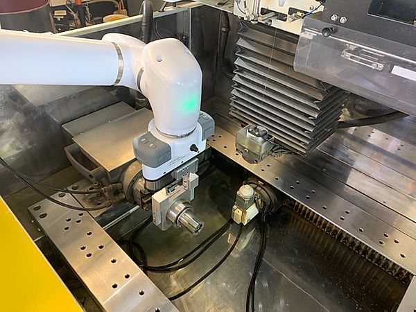
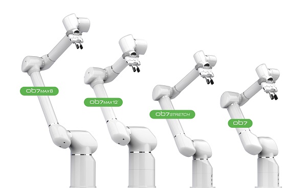
Most cobots have six joints (axes), which provides significant reach but limits how they can approach a machine without blocking operator access. A 7-axis cobot like the OB7 has an additional joint that functions like a human elbow. It can reach around obstacles, access the machine from the side rather than directly in front, and fit into tighter spaces without requiring the work area to be redesigned.
|
6-Axis Cobot |
7-Axis Cobot (OB7) |
|
|---|---|---|
|
Typical placement |
In front of machine door |
Beside machine door |
|
Operator access when cobot is in position |
Restricted |
Open |
|
Space requirement |
Larger footprint |
More compact |
|
Workspace redesign typically needed? |
Yes |
Rarely |
|
Key advantage |
Simpler reach envelope |
Side-door approach, elbow-like flexibility |
Additional layout questions to resolve before the cobot arrives:
Absolute’s automation engineers conduct on-site workspace assessments before every integration, evaluating cobot placement, material flow, and operator access so the cell is designed for productivity from day one.
Step 2: Know the Difference Between Installing and Integrating
This is where more implementation projects run into trouble than any other step. The terms “installing” and “integrating” are used interchangeably in the industry, but they describe fundamentally different scopes of work — and different price points.
|
Installing |
Integrating |
|
|---|---|---|
|
What it means |
Unpacking, assembling, commissioning, and training |
Setting the cobot up to communicate directly with the CNC machine and sequence between them |
|
What it includes |
Physical setup, initial configuration, basic operator training |
Programming, I/O wiring, M-code setup, gripper development, load/unload stations |
|
CNC control knowledge needed |
No |
Yes, and it differs for every control brand (Haas, FANUC, Mitsubishi, Siemens) |
|
Who can do it |
Most cobot dealers |
Integrators with specific CNC machine tool communication experience |
|
Typical cost relative to the cobot |
Low |
Can equal or exceed the cost of the cobot itself |
The M-Code Problem
When a cobot is wired into a CNC machine’s I/O (rather than just placed near it), the two pieces of equipment communicate through M-codes — programmed instructions in the CNC control. A simple machine-tending cycle might require this sequence:
- The cobot picks up a part and moves to the load position.
- The cobot waits for an M-code signal indicating the machine door is open and the machine is idle.
- The cobot loads the part.
- The CNC holds on that M-code until it receives a completion signal from the cobot confirming the part is loaded and the arm has cleared.
- The machine begins the cycle.
Every additional function — chuck open/close, door open/close, vise open/close — requires its own M-code. Newer CNC machines typically have enough built in. Older machines often do not. When additional M-codes are needed, the CNC machine distributor’s service technicians must install them. Many generic integrators do not know to check for this until they are already on-site.
According to Dave Zunis, Absolute’s Director of Service and Applications Engineering: “Most integrators will say they can integrate a cobot to any CNC machine tool. However, this is often not the case. The technician integrating the cobot to the CNC needs to be able to read and understand the ladder logic within the CNC control. If they don’t, then they will use your time and money to learn it.”
Absolute’s automation engineers have been integrating automatic equipment with CNC controls since 1988, across Haas, FANUC, Mitsubishi, Siemens, and other platforms.
The Master Interface Unit (MIU): A Simpler Path for Many Shops
For shops concerned about the complexity or cost of full CNC integration, Absolute Machine Tools’ patented Master Interface Unit (MIU) provides a simplified connection between the OB7 and virtually any CNC machine without custom M-code programming or ladder logic modification. The MIU is particularly valuable for shops with older machines or limited in-house engineering resources, and it significantly reduces the integration timeline and cost for most standard machine tending applications.
What to Ask Any Integrator Before Signing:
- Do they have experience specifically with CNC machine tool communication, or primarily industrial robot installations?
- Can they read and modify the ladder logic on your specific CNC control?
- Will they do the integration work themselves, or subcontract it?
- Is training included in the quoted price, and how many hours does it cover?
- Will they provide ongoing support after go-live, or does the engagement end at installation?
Timeline: From signed order to first production cycle, a standard single-machine cobot cell typically runs 6–12 weeks, depending on cell complexity, machine type, fixturing requirements, and whether MIU or full CNC integration is used.
Step 3: Plan How Parts Will Be Staged and Presented
Part staging is the most underestimated cost in any cobot implementation. Many shops reach this step only after the cobot has arrived. That is too late.
The cobot needs to pick parts from a consistent, repeatable location every cycle. That requires fixturing: a tray, chute, table, conveyor, or custom device that holds parts in registration — the same position and orientation every time. Without fixturing, the cobot does not know where to find the part.
Fixturing Options by Complexity:
- A flat tray with machined pockets holding parts in a grid (simple, low cost, manual refill)
- A chute or slide that gravity-feeds parts into a pick position one at a time
- A pneumatic parts release mechanism that presents parts automatically
- A full conveyor system for continuous high-volume feeding
- Bin picking with a vision system (covered in Step 8)
The right solution depends on part geometry, batch size, cycle time, and budget. Fixturing is also a real cost that belongs in the ROI calculation from the beginning — use the cobot ROI framework to capture fixturing as a line item before the project is scoped and budgeted.
Before the cobot ships, the staging plan and all fixturing details belong in a written Scope of the Project. Also resolve:
- Can the cobot reach the staging area from its position beside the machine door?
- Can the operator refill the staging area during a run without entering the cobot’s work envelope?
- For lights-out operation, how many parts does the staging area hold, and does that cover the full planned unattended run? See the lights-out manufacturing guide for more on planning for overnight production.
Part presentation is one of the most underestimated decisions in any cobot implementation. Get it wrong and the cell fights the process every day. Get it right and the whole cell runs.
Step 4: Choose the Right End-Effector
The end-effector — also called a gripper or end-of-arm tooling (EOAT) — is the business end of the cobot. It is what contacts and handles the part. Choosing the wrong one is one of the most common implementation mistakes, and one of the most fixable.
The three main types:
Grippers are the most common for CNC machine tending. They open and close around a part to pick it up and release it. Available in pneumatic, electronic, mechanical, and hydraulic versions. Electronic grippers offer the most flexibility for varying part geometries. Pneumatic grippers are most common for production machine tending.
Process tools perform work on the part itself: welding, machining, painting, deburring. These are the right choice when the cobot is doing something other than loading and unloading a CNC machine.
Sensors such as cameras and other sensing devices are used for inspection, bin picking, and part verification. Sensors as end-effectors are covered in Step 8 (Optional).
Consider Payload and Inertia
The end-effector weight counts against the cobot’s rated payload, as does the part being held. If the part is held close to the face plate and the end-effector is compact, the cobot’s rated payload applies directly. If the part is held at distance from the face plate, the center of gravity shifts and inertia reduces the effective payload. The full calculation: end-effector weight + part weight + inertia effect. If that total exceeds the cobot’s payload rating, performance will be affected.
How to choose:
- Determine the specific action the cobot will perform (pick, place, load, unload)
- Match the end-effector type to that action
- Calculate total payload
- Pick the end-effector that works best for this specific job, not the one that seems most universal
That last point matters: a multi-purpose end-effector that can handle any job will be outperformed by one optimized for the current job. End-effectors are reasonably priced and easy to swap out. Get the right one for this job.
Communication Protocols
Different end-effectors use different communication protocols. Confirm with your cobot provider which end-effectors communicate natively with your specific cobot. Verify compatibility before purchase.
The end-effector should be selected and ordered before the cobot arrives. A good automation integrator will study the actual parts and make specific recommendations. If they recommend an end-effector without having seen the part geometry, find someone else.
Step 5: Establish a Maintenance Routine Before Day One
Most manufacturers have a maintenance routine for their CNC machines. The cobot deserves the same treatment , and the routine is simpler than most shops expect.
IP Ratings and the CNC Environment
The environment the cobot operates in directly affects how rigorous the maintenance routine needs to be. IP (Ingress Protection) ratings classify how well a cobot is sealed against solids and liquids.
The rating has two digits: the first covers solid particle intrusion (dust, chips), the second covers liquid intrusion (coolant, water, cutting fluid). An IP64-rated cobot is fully dust-protected (6) and protected against liquid splashed from any direction (4). IP65 adds protection against low-pressure liquid jets. IP68 means submersible.
Even with a high IP rating, a cobot in a chip-heavy CNC environment benefits from a daily wipe-down. Chips and coolant that accumulate around joints and wrist flanges will eventually work their way in regardless of rating.
Daily Maintenance Checklist
Build these checks into the shift startup routine before the cobot is ever switched on for the first time. They take less than five minutes and prevent the majority of unplanned downtime.
- Check for peeling paint or cracks on covers. Touch up paint immediately; order replacement covers if cracked.
- Check joints for oil or grease seepage. Seepage indicates a potential O-ring failure, loose bolts, or casting crack. Investigate before proceeding.
- Check for vibrations or abnormal noises during startup. Sources include defective motors, damaged cables, foreign matter in a gear or bearing, or loads that have exceeded inertia limits.
- Check ventilation and chip fans for blockage. Chips and oil buildup cause overheating, especially when an onboard computer is present.
- Check that all cable connections are secure. Connections loosen during operation.
- Check for alarms or warning codes and log any that appeared since the previous shift.
- Check that the end-effector is secure and mounting bolts are tight. Mounting bolts loosen during operation.
- Check the cobot’s base mounting bolts. Adhesives used to secure hardware weaken over time.
- Check for any visible external damage. Log it, investigate the cause, and confirm nothing else was affected before resuming production.
- Treat the cobot as a member of the production team. A significant investment in money, time, and training depends on this equipment performing reliably. A well-maintained cobot is a productive cobot.
Step 6: Conduct a Risk Assessment
OSHA has not published specific risk assessment regulations for cobots, though that is expected to change. Even without a formal regulation, conducting a thorough risk assessment before deployment protects employees, reduces liability, and meets the intent of ISO/TS 15066:2016, the international standard governing collaborative robot operations in shared workspaces.
Two Types of Human-Robot Contact
ISO/TS 15066 distinguishes between two contact scenarios:
- Transient contact: The operator’s body part is not clamped and can recoil or pull away from the moving cobot. Lower-risk scenario.
- Quasi-static contact: The operator’s body part can be clamped between a moving part of the cobot and another fixed or moving element of the cell. Higher-risk scenario — requires more careful cell design.
Collaborative Speed Limits
Everyone working in a shared space with a cobot needs to understand one critical parameter: in collaborative mode, the cobot’s speed must stay at or below 10 inches per second (250mm/second). Anything above that threshold changes the workspace classification to an industrial robot environment and requires additional safeguarding.
Common Hazards to Assess Even in Collaborative Mode
- Entanglement: Hair, clothing, gloves, jewelry, shop rags, or other items near the cobot’s joints and wrist during operation
- Electrical: Overloaded circuits, damaged cables, or exposed wiring in or around the cell
- Ergonomic: Poor lighting in and around the cell that increases operator error or fatigue
- Slip, trip, fall: Uneven floor surfaces, cables on the floor, or poor housekeeping around the cell perimeter
Risk Reduction Measures
- Where hazards can be eliminated through design changes, change the design first
- Where design changes are insufficient, use guarding
- Where guarding is insufficient, add engineering controls, PPE, warnings, and signage
- Complete the risk assessment sign-off sheet included in the cobot manufacturer’s documentation before deployment, not after
- Conduct a fresh risk assessment every time the cobot moves to a new location or a new application
Absolute’s automation engineers build risk review into every integration project to ensure the cell meets ISO/TS 15066 collaborative operation standards from the start. Contact the automation team →
Step 7: Review Before You Go Live
The review step is the easiest to skip because nothing gets installed or connected. It is also the step that separates implementations that run cleanly from day one from those that surface problems in production that should have been caught in planning.
Before go-live, confirm each of the following:
- Workspace assessment complete, cell layout finalized
- Part staging and fixturing in place, tested with actual production parts
- End-effector selected, ordered, and tested on the part
- CNC integration (or MIU setup) complete and machine-cobot communication verified through a full test cycle
- Maintenance checklist created and operators trained on it
- Risk assessment completed and signed off
- At least one full attended test cycle run to confirm part quality, cycle time, and process consistency
Start Simple
Even after all seven steps are complete, start with the easiest job on the floor, not the most important one. A simple, proven job running with the cobot builds operator confidence and lets the team learn the system before the stakes are higher.
BIC Precision started with short-run batches of 500 to 7,000 parts, well below the volumes most shops assume cobots require. Getting the simpler application running first made the path to more complex jobs clear. Read the BIC Precision case study →
The Most Common Cobot Implementation Mistakes
These are the failure points that appear most frequently in shops that bought a cobot and struggled to deploy it:
1. Buying the cobot before scoping the cell. The cobot arrives, and the shop realizes nobody has figured out fixturing, staging, or the CNC interface. The cobot sits in a crate. Scope the full cell first, before the purchase order.
2. Choosing an integrator without CNC machine tool experience. Many automation integrators come from industrial robot backgrounds. They can install a cobot, but they cannot navigate CNC ladder logic or build M-code sequences. Verify CNC-specific experience before signing.
3. Underestimating fixturing and staging costs. Fixturing for a cobot cell can run from a few hundred to several thousand dollars depending on part geometry and batch size. It is a real cost that belongs in the ROI calculation from day one. See cobot ROI framework →
4. Skipping the risk assessment. The absence of a specific OSHA regulation for cobots is not the absence of a hazard. ISO/TS 15066 provides the standard. Conduct the assessment before deployment.
5. Starting with the most complex or most critical job. The first cobot application is the easiest job that can demonstrate a return, not the one the shop needs most urgently. High-complexity or high-tolerance applications come after the team is comfortable with the system.
6. No maintenance routine on Day 1. A cobot without a daily maintenance routine will eventually stop. Building the checklist into shift startup from the first day prevents the unplanned downtime that comes from neglect.
7. Not planning for lights-out from the start. If the long-term goal is unattended overnight operation, the cell needs to be designed for it from the beginning: staging capacity, auto door kit, remote monitoring, tooling life management. Retrofitting for lights-out is always harder than building for it upfront. See the lights-out manufacturing guide →
Real-World Implementation Results
Swiss Productions — Ventura, California
A precision screw machine shop that added a cobot to their Haas Mill. Originally getting 9 hours of daily production with an operator loading and unloading every 7-8 minutes. After OB7 implementation, production reached 76 hours per week, adding 32 hours of unattended production plus recovery of time previously lost during breaks. A second OB7 has since been added. Read the Swiss Productions case study →
True Precision Machining
A wire EDM shop where OB7 machine tending allowed a 500-part job to be completed in 3.5 days instead of a full week. “We finished a job in 3.5 days that would have taken a week to complete,” said Marvin Rodriguez, VP of True Precision Machining. Read the True Precision case study →
BIC Precision
A small job shop running batches of 500 to 7,000 parts, well below what most shops assume cobots require. OB7 tending two Doosan lathes, including secondary operations, freed the operator to run two additional machines simultaneously. Read the BIC Precision case study →
When to Work With an Automation Integrator
Not every cobot implementation requires a full integration engagement. The right level of support depends on the application and what expertise exists in the shop.
A shop may be able to handle implementation without an integrator if:
- The cobot will push a start button rather than wiring into the CNC’s I/O, a valid approach for many applications.
- The fixturing is simple and the shop has someone comfortable building it.
- The application does not require the cobot and CNC machine to exchange signals beyond a basic start/stop.
An experienced CNC integrator is needed when:
- The cobot needs to communicate directly with the CNC control via M-codes.
- The machine is older and M-code capacity is unknown.
- The cell involves multiple machines, multiple part types, or a lights-out requirement.
- Nobody in the shop has experience with cobot programming or CNC ladder logic.
The difference between a smooth integration and a frustrating one usually comes down to whether the integrator truly understands CNC machine tool communication. Absolute’s automation engineers have been integrating automatic equipment with CNC controls since 1988, across Haas, FANUC, Mitsubishi, Siemens, and others. Every project begins with a written scope so there are no surprises on cost, training, or capability.
Step 8 (Optional) — Should You Add Vision to Your Cobot Cell?
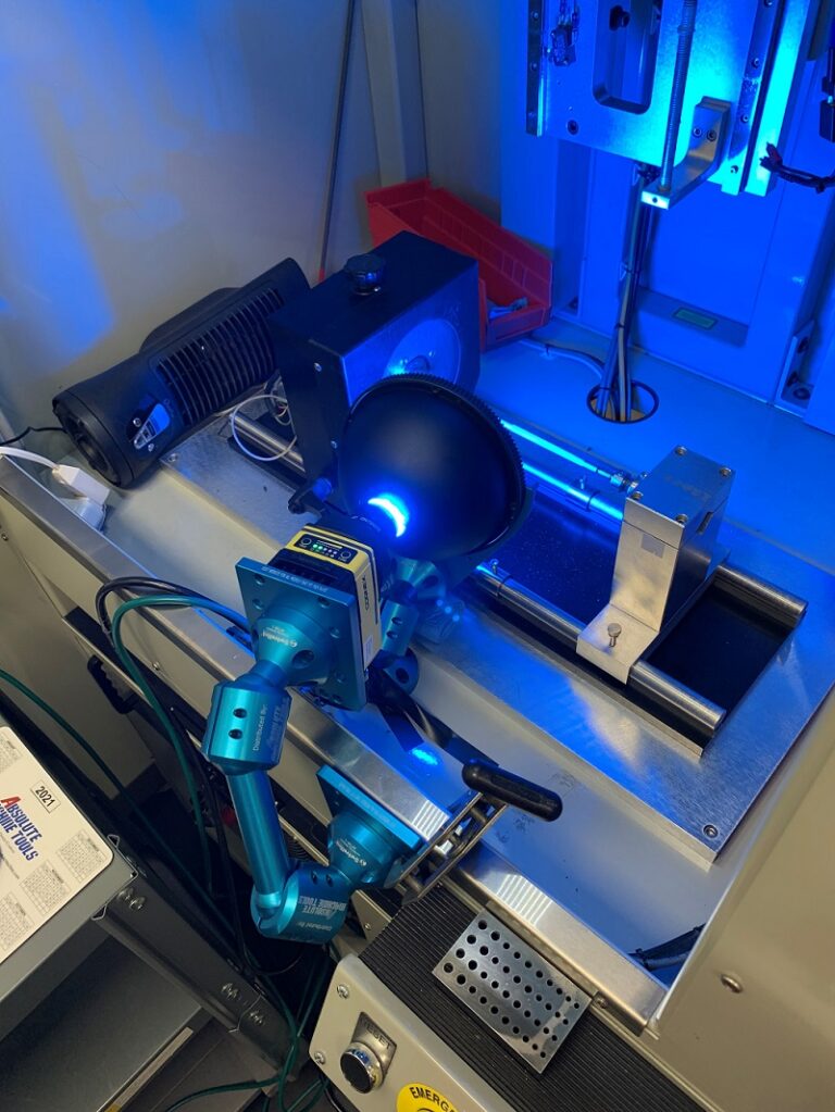
Vision is not required for most CNC machine tending applications. If the cobot loads and unloads parts that arrive in a consistent, known orientation via fixturing, vision adds cost and complexity without meaningful return.
Vision becomes worth evaluating when:
- Parts arrive in a bin in random orientations (bin picking requires 3D vision to locate and orient parts)
- The application includes in-line quality inspection after machining
- Part identification is needed to distinguish between similar part numbers on a mixed production line
2D vs. 3D Vision: A Quick Decision Framework
|
2D Vision |
3D Vision |
|
|---|---|---|
|
Processing speed |
Faster |
Slower |
|
Best for |
Flat geometry, in-line inspection, part identification |
Complex geometry, bin picking with significant depth variation |
|
Setup complexity |
Lower |
Higher |
|
Cost |
Lower |
Higher |
|
Typical machine tending use |
Post-machining part inspection |
Bin picking of raw stock |
For most CNC machine tending implementations, vision is a Phase 2 addition, something to evaluate once the basic cell is running and the team is comfortable with the system. Get the cell running first, then assess whether vision delivers a measurable return on the specific process.
Absolute’s automation engineers are certified across multiple vision platforms including Cognex, Keyence, and Omron. Contact the automation team to discuss whether vision belongs in your implementation.
Cobot Implementation FAQs
Ready to Implement A Cobot in Your Job Shop?
Most shops that are considering a cobot already have the right application for it. The gap is usually not the technology; it is having a clear plan for the cell around it.
Absolute’s automation engineers work with shops of all sizes to scope, integrate, and support CNC automation from a single cobot cell to full lights-out systems. See Absolute’s automation solutions → or call 800-852-7825.