When evaluating a CNC rotary table, most buyers focus on indexing accuracy and table diameter. Braking mechanism often gets overlooked — but it’s one of the most consequential design decisions in the entire unit. The brake is what holds your workpiece rigidly in position while the spindle is cutting. A weak or poorly designed brake means deflection, chatter, and part inaccuracy. A well-engineered one disappears into the background and lets you cut aggressively with confidence.
This post explains how hydraulic full-circumference braking works, why it outperforms traditional disk braking systems, and what that difference means in practice for your shop.
How Traditional Disk Braking Works — and Where It Falls Short

Most entry-level rotary tables use a disk brake design: a single brake disk is clamped when the table locks, similar in principle to an automotive disc brake. The clamping force acts on a limited surface area, which limits how much rigidity the system can generate.
Under heavy cutting loads — particularly interrupted cuts, face milling, or machining hard materials — the table can experience micro-deflection at the brake interface. This shows up as part inaccuracy, poor surface finish, or tool chatter. The problem compounds when machining large or heavy workpieces, where the moment arm increases the effective force the brake has to resist.
Disk brakes are also typically actuated pneumatically. While adequate for light duty work, air pressure systems are subject to pressure variation across a shop, and clamping force can fluctuate as a result.
How Hydraulic Full-Circumference Braking Works
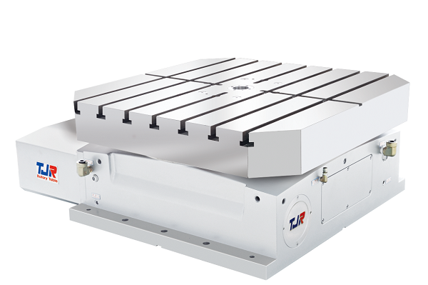
TJR rotary tables use a fundamentally different approach: 360-degree circumference clamping, actuated hydraulically.
Instead of clamping a single disk, the brake engages the full circumference of the table — distributing clamping force evenly around the entire perimeter. Hydraulic actuation applies that force consistently and at significantly higher pressure than pneumatic systems can achieve.
The result is a braking system that is:
Why This Matters for Real Cutting Applications
The practical impact of hydraulic full-circumference braking is most noticeable in three situations:
Heavy interrupted cuts. When a face mill or end mill is repeatedly entering and exiting a workpiece, the impulse forces at each entry can cause a disk-brake table to shift subtly. A full-circumference hydraulic brake locks the table hard enough that these forces are absorbed without movement.
Large or heavy workpieces. The bigger and heavier the part, the more torque is acting on the locked table. Full-circumference clamping handles this proportionally better than a disk brake because the clamping force scales with the full perimeter rather than a fixed contact patch.
Tight-tolerance work. When positioning accuracy at each index directly affects part quality — bolt patterns, splined features, gear teeth — the last thing you want is brake-induced deviation between positions. Hydraulic clamping eliminates that variable.
Hydraulic vs. Pneumatic: A Practical Comparison
|
Feature |
Pneumatic Disk Brake |
Hydraulic Full-Circumference |
|---|---|---|
|
Clamping surface |
Single disk |
Full 360° perimeter |
|
Actuation medium |
Compressed air |
Hydraulic fluid |
|
Clamping force consistency |
Varies with shop air pressure |
Consistent and high |
|
Rigidity under heavy cuts |
Moderate |
High |
|
Drivetrain strain |
Higher |
Lower |
|
Best suited for |
Light-to-medium duty |
Medium-to-heavy duty |
Clamping Torque: What the Numbers Actually Mean
One of the clearest ways to evaluate a rotary table’s braking system is clamping torque — the maximum rotational force the brake can resist while the table is locked. To give a sense of the range: the HR-255 (a 10″ table suited to smaller VMCs) delivers 70 kg-m of clamping torque, while the HR-630 (a 24.8″ table built for heavy-duty work) reaches 800 kg-m. Repeatability across the HR Series is ±4 arc-seconds — meaning after every index cycle, the table returns to within 4 arc-seconds of its target position, consistently.
To put those figures in context: 800 kg-m of clamping torque on a large table means it effectively becomes a rigid extension of the machine structure during cutting — capable of holding firmly against the kind of interrupted cuts and high material removal rates that would cause a less rigid system to shift. For the full clamping torque ratings across the HR Series by table size, see the HR Series product page.
Maintenance and Long-Term Reliability
Hydraulic systems carry a reputation for complexity, but in practice the TJR HR Series hydraulic brake is a low-maintenance design. The brake engages and disengages automatically as part of the normal CNC cycle — there are no manual adjustments required during operation, and no consumable brake components that wear out the way friction-based disk systems do.
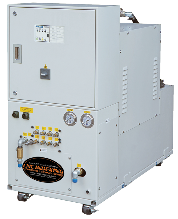
The hydraulic system is self-contained within the table housing. It does not require a separate hydraulic power unit — the table connects to a standard hydraulic supply line, which is typically available on any VMC already equipped with a hydraulic tool clamp or workholding system. For machines without an existing hydraulic supply, a small standalone hydraulic unit can be added.
Routine maintenance is straightforward: periodic checks of hydraulic fluid level and line connections, and scheduled inspection of the worm gear and bearing system per TJR’s maintenance intervals. Because the hydraulic brake absorbs cutting forces directly — rather than transmitting them through the worm gear and servo motor — it reduces wear on those components and extends their service life considerably. TJR rates the high-tensile brass worm gear at an estimated 10-year wear life, more than twice the service life of aluminum bronze alternatives.
All new TJR rotary tables come with a 3-year parts warranty, and Absolute Machine Tools maintains a full inventory of genuine TJR repair parts for in-house service and rebuild if ever needed.
How the Hydraulic Brake and Dual Lead Worm Gear Work Together
The hydraulic braking system doesn’t operate in isolation — it’s designed as part of an integrated mechanical system alongside TJR’s dual lead worm gear. Understanding how the two interact explains why TJR tables perform the way they do over long service life.
The dual lead worm gear handles positioning: its one-piece wormshaft, manufactured with two slightly different lead angles on opposite flanks, allows backlash to be adjusted from a defined maximum down to zero. The larger pitch circle diameter reduces pressure on the contact surface, and the full tooth depth engagement creates a larger contact area than conventional worm gear designs — resulting in a stronger, more accurate drive system.
The hydraulic brake handles rigidity during cutting: once the table has indexed to position, the full-circumference hydraulic clamp engages and locks the table independently of the worm gear. This is the key point — the brake carries the cutting loads so the worm gear doesn’t have to. In systems without a high-clamping-force brake, the worm gear is left to resist the forces generated during machining, which accelerates wear on the gear teeth and degrades long-term indexing accuracy.
In the TJR design, the worm gear drives and positions; the hydraulic brake holds and protects. The result is a system where both components remain accurate longer because neither is being asked to do the other’s job.
Hydraulic vs. Pneumatic Braking: Choosing the Right System for Your Application
TJR rotary tables are available in both hydraulic brake (HR Series) and pneumatic brake (AR Series) configurations. Neither is universally superior — the right choice depends on your application, your machine, and your budget.
The AR Series (pneumatic brake) is likely the better fit if:
The HR Series (hydraulic brake) is the better fit if:
The honest summary: for a large portion of job shop work, a pneumatic AR Series table will perform well and represent excellent value. The hydraulic HR Series earns its cost premium in demanding applications — heavy cuts, tight tolerances, high volumes, or hard materials — where the additional clamping torque and drivetrain protection pay back over time.
Is a Hydraulic Brake Rotary Table Right for Your Shop? Contact Us to Find Out
Braking is not a feature to compromise on if your shop runs heavy parts, hard materials, or tight tolerances. The combination of hydraulic actuation and full-circumference clamping in TJR rotary tables delivers the rigidity and repeatability that disk-brake designs simply can’t match in demanding applications.
Absolute Machine Tools offers the complete TJR rotary table lineup, including 4th axis, tilting, and indexing configurations — all with hydraulic full-circumference braking as standard. If you’re unsure which configuration is right for your specific application, we can help you evaluate both options based on your machine, your parts, and your production requirements. Contact us today to discuss which table is the right fit for your machine and your work.