TJR HR Hydraulic Brake Series
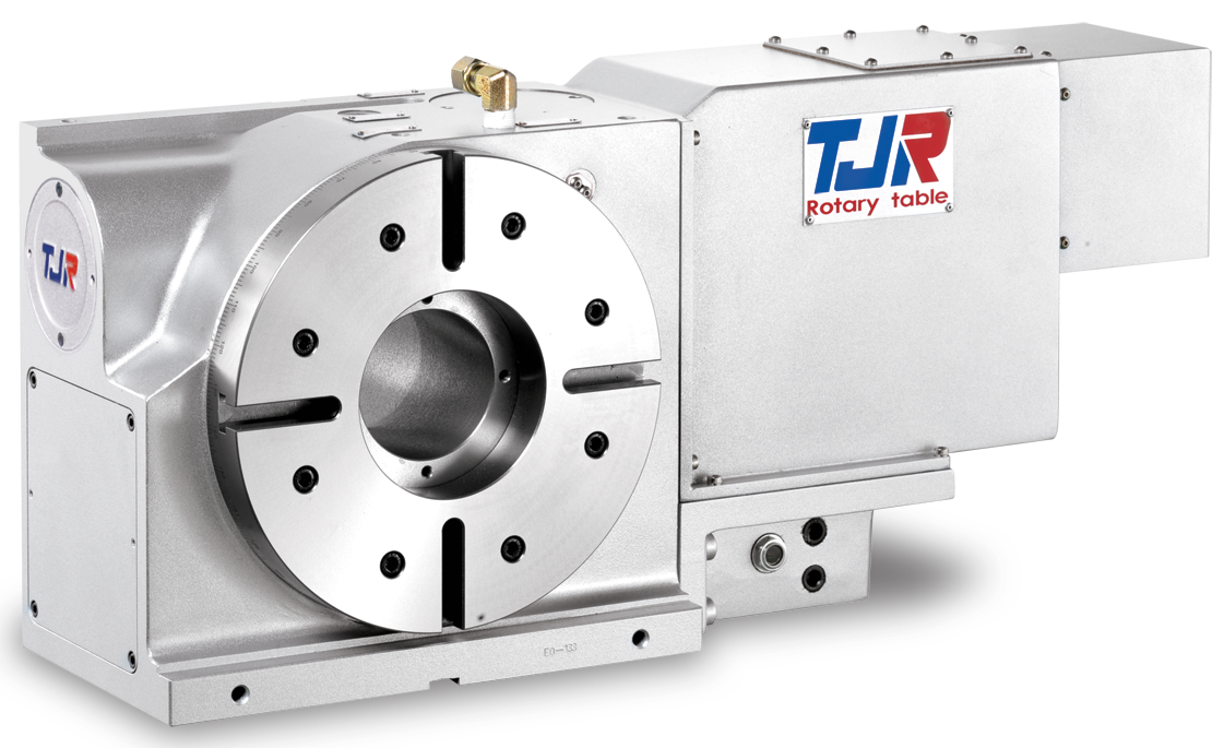
The HR-Series is TJR’s hydraulic brake series of standard 4th axis rotary tables that is offered in multiple sizes. The sizes range from 210mm (8.26”) to 800mm (31.49”) face plate diameter. The HR series offers a Big Bore through hole design that delivers high rigidity and offers a larger work space for piece set up with fixtures and can be adjusted by using a mandrel sleeve.
These units are capable of being mounted in both the vertical and horizontal position. The HR series also offer a reduced sheet metal design that is suitable for tight vertical or horizontal applications.
The HR series is manufactured with a large radial-axial preloaded bearing system for high rigidity that can perform heavy cutting. The HR-Series uses a dual lead worm shaft and worm gear to ensure long term indexing accuracy in both directions.
Specifications
| Item / Model |
Unit
|
HR-210
Request a Quote
|
HR-255
Request a Quote
|
HR-320
Request a Quote
|
HR-400
Request a Quote
|
HR-500R
Request a Quote
|
HR-630R
Request a Quote
|
HR-800R
Request a Quote
|
|---|---|---|---|---|---|---|---|---|
|
Table Diameter |
mm |
Ø 210 |
Ø 255 |
Ø 320 |
Ø 400 |
Ø 500 |
Ø 630 |
Ø 800 |
|
Diameter of Table Central Hole |
mm |
Ø 67 |
Ø 110 |
Ø 150 |
Ø 150 |
Ø 250 |
Ø 325 |
Ø 395 |
|
Inner Diameter of Mandrel Sleeve |
mm |
Ø 40H7 |
Ø 80H7 |
Ø 120H7 |
Ø 120H7 |
Ø 220H7 |
Ø 280H7 |
Ø 350H7 |
|
Diameter of Center Through Hole |
mm |
Ø 40 |
Ø 80(Big Bore) |
Ø 120(Big Bore) |
Ø 120(Big Bore) |
Ø 220 (Big Bore) |
Ø 280 (Big Bore) |
Ø 350 (Big Bore) |
|
Center Height (Vertical) |
mm |
160 |
160 |
210 |
255 |
310 |
400 |
470 |
|
Table Height (Horizontal) |
mm |
152 |
200 |
235 |
250 |
290 |
325 |
350 |
|
Table T-slot Width |
mm |
12H7 |
12H7 |
14H7 |
14H7 |
18H7 |
18H7 |
18H7 |
|
Guide Block Width |
mm |
18h7 |
18h7 |
18h7 |
18h7 |
18h7 |
18h7 |
18h7 |
|
Min. Increment |
deg. |
0.001 |
0.001 |
0.001 |
0.001 |
0.001 |
0.001 |
0.001 |
|
Indexing Precision |
sec. |
20 |
15 |
15 |
15 |
15 |
15 |
15 |
|
Repeatability |
sec. |
4 |
4 |
4 |
4 |
4 |
4 |
4 |
|
Clamping System (Hydraulic) |
kg/cm2 |
25 |
35 |
35 |
35 |
35 |
35 |
35 |
|
Clamping Torque |
kg-m |
35 |
70 |
115 |
200 |
370 |
800 |
800 |
|
Servo Motor Model (FANUC) |
– |
α4i/α8i/ß8is(Taper shaft) |
α8i/ß8is(Taper shaft) |
α12i/ß22is(Straight shaft) |
α12i/ß22is(Straight shaft) |
α12i / ß22is (Direct Shaft without Key) |
α12i / ß22is (Direct Shaft without Key) |
α22i (Direct Shaft without Key) |
|
Servo Motor Model (MITSUBISHI) |
– |
HF-54/104 (Taper shaft) |
HF-104/154 (Taper shaft) |
HF-204 (Straight shaft) |
HF-204 (Straight shaft) |
HF-204 (Direct Shaft without Key) |
HF-204 (Direct Shaft without Key) |
HF-204 (Direct Shaft without Key) |
|
Speed Reduction Ratio |
– |
1:90 |
1:120 |
1:120 |
1:120 |
1:180 |
1:180 |
1:180 |
|
Max. Rotation Rate of Table (Calculate with Fanuc α Motor) |
r.p.m |
44.4 |
33.3 |
25 |
25 |
16.6 |
16.6 |
11.1 |
|
Allowable Inertia Load Capacity (Horizontal) |
kg.cm.sec2 |
8.3 |
20.3 |
44.8 |
100 |
187.5 |
396.9 |
1200 |
|
Allowable Workpiece Load (Vertical) |
kg |
75 |
100 |
150 |
200 |
250 |
400 |
800 |
|
Allowable Workpiece Load (with Tailstock) |
kg |
150 |
250 |
350 |
500 |
600 |
800 |
1500 |
|
Allowable Workpiece Load (Horizontal) |
kg |
150 |
250 |
350 |
500 |
600 |
800 |
1500 |
|
Allowable Load with Rotary Table Clamping (F) |
kgf |
1450 |
2000 |
3000 |
4000 |
4000 |
5000 |
5000 |
|
Allowable Load with Rotary Table Clamping (FxL) |
kgf.m |
100 |
112 |
300 |
400 |
500 |
850 |
1000 |
|
Allowable Load with Rotary Table Clamping (FxL) |
kgf.m |
35 |
70 |
115 |
200 |
370 |
800 |
800 |
|
Strength of worm gears (Rotary axis)  |
kg.m |
18 |
55 |
80 |
170 |
250 |
420 |
800 |
|
Net Weight (servo motor excluded) |
kg |
55 |
109 |
204 |
315 |
405 |
692 |
– |