Rear Motor Mount Rotary Table
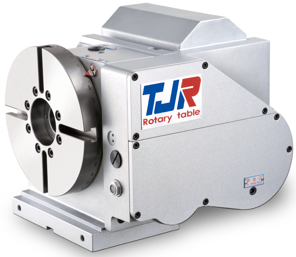
TJR’s AR Series rear motor mount rotary table shares the same robust platform as the standard AR Series 4th axis rotary table, configured specifically for applications where a back-mounted motor better suits your machine’s work envelope or fixturing requirements. Available in sizes ranging from 125mm (4.92″) to 250mm (9.84″) face plate diameter.
Like all AR Series rotary tables, the rear mount configuration supports full 4th axis integration directly into the CNC machine control, or standalone indexing operation using TJR’s SAC (Single Axis Controller). Vertical and horizontal mounting positions are both supported, and right-hand and left-hand motor configurations are also available — all with a pneumatic braking system for secure positioning under load.
The radial-axial preloaded bearing system delivers the high rigidity needed for both light and heavy cutting operations, and the dual lead worm shaft and worm gear design maintains long-term indexing accuracy in both directions.
Specifications
| Item / Model |
Unit
|
AR-125B
Request a Quote
|
AR-170B
Request a Quote
|
AR-210B
Request a Quote
|
AR-250B
Request a Quote
|
|---|---|---|---|---|---|
|
Table Diameter |
mm |
Ø 125 |
Ø 170 |
Ø 210 |
Ø 250 |
|
Diameter of Table Central Hole |
mm |
Ø 35H7 |
Ø 67 |
Ø 67 |
Ø 67 |
|
Inner Diameter of Mandrel Sleeve |
mm |
– |
Ø 40H7 |
Ø 40H7 |
Ø 40H7 |
|
Diameter of Center Through Hole |
mm |
Ø 25 |
Ø 40 |
Ø 40 |
Ø 40 |
|
Center Height (Vertical) |
mm |
110 |
135 |
160 |
160 |
|
Table Height (Horizontal) |
mm |
– |
– |
– |
– |
|
Table T-slot Width |
mm |
12H7 |
12H7 |
12H7 |
12H7 |
|
Guide Block Width |
mm |
14h7 |
18h7 |
18h7 |
18h7 |
|
Min. Increment |
deg. |
0.001 |
0.001 |
0.001 |
0.001 |
|
Indexing Precision |
sec. |
40 |
20 |
20 |
20 |
|
Repeatability |
sec. |
4 |
4 |
4 |
4 |
|
Clamping System (Pneumatic) |
kg/cm2 |
6 |
6 |
6 |
6 |
|
Clamping Torque |
kg-m |
13 |
31 |
31 |
31 |
|
Servo Motor Model (FANUC) |
Taper shaft |
α2i / ß4is |
α4i / α8i / ß8is |
α4i / α8i / ß8is |
α4i / α8i / ß8is |
|
Servo Motor Model (MITSUBISHI) |
Taper shaft |
HF-75 / 105 |
HF-54 / 104 |
HF-54 / 104 |
HF-54 / 104 |
|
Speed Reduction Ratio |
– |
1:60 |
1:90 |
1:90 |
1:90 |
|
Max. Rotation Rate of Table (Calculate with Fanuc α Motor) |
r.p.m |
83.3 |
44.4 |
44.4 |
44.4 |
|
Allowable Inertia Load Capacity (Horizontal) |
kg.cm.sec2 |
2 |
2.7 |
4.1 |
5.9 |
|
Allowable Workpiece Load (Vertical) |
kg |
50 |
75 |
75 |
75 |
|
Allowable Workpiece Load (with Tailstock) |
kg |
100 |
150 |
150 |
150 |
|
Allowable Workpiece Load (Horizontal) |
kg |
– |
– |
– |
– |
|
Allowable Load with Rotary Table Clamping (F) |
kgf |
1000 |
1450 |
1450 |
1450 |
|
Allowable Load with Rotary Table Clamping (FxL) |
kgf.m |
45 |
100 |
100 |
100 |
|
Allowable Load with Rotary Table Clamping (FxL) |
kgf.m |
13 |
31 |
31 |
31 |
|
Strength of worm gears (Rotary axis)  |
kg.m |
9 |
18 |
18 |
18 |
|
Net Weight (servo motor excluded) |
kg |
– |
60 |
65 |
72 |