Manual Tilt Rotary Table
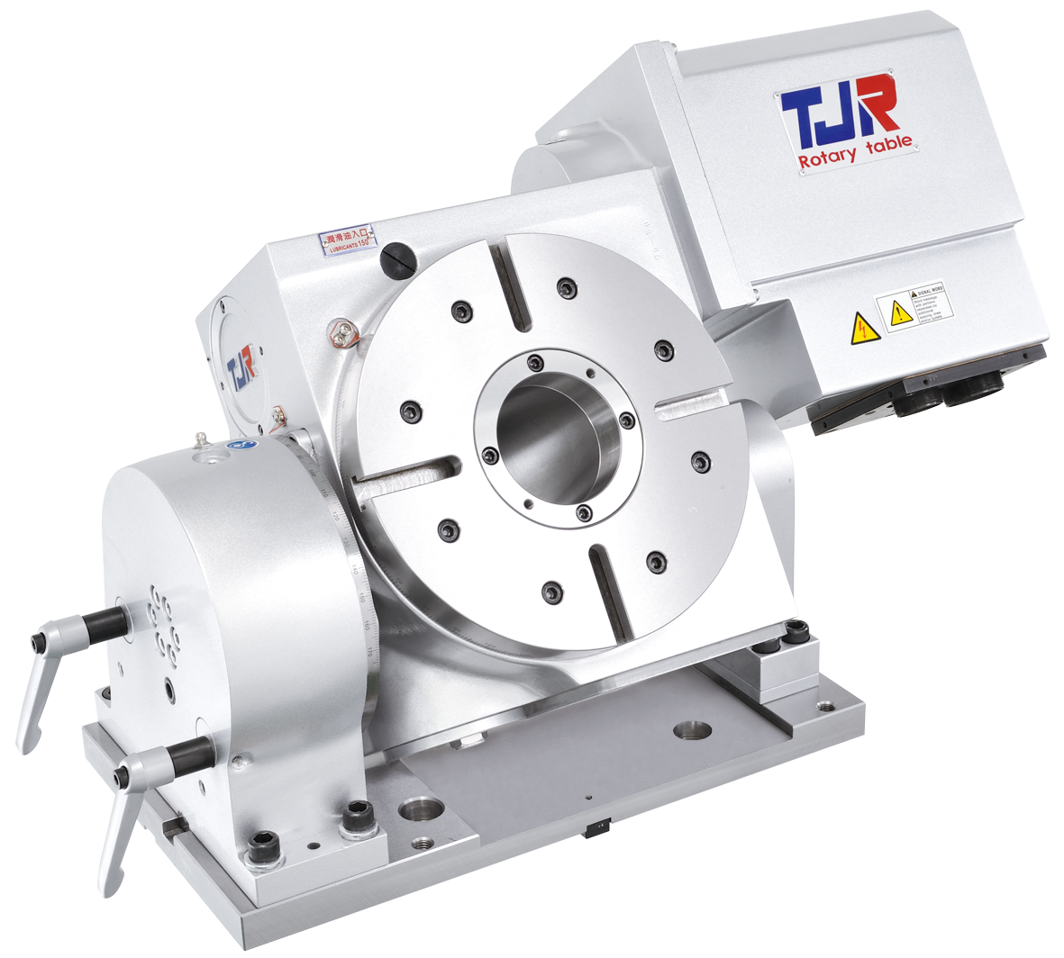
The rotating axis of the MTHR rotary table can be intergraded into a CNC machine control as a full 4th axis or it can be operated as an indexer by utilizing TJR’s SAC (Single Axis Controller). The MTHR unit is manufactured with a large radial-axial preloaded bearing system for high rigidity that can perform light or heavy cutting.
The MTHR is TJR’s 1 degree manual tilt rotary table offering that employs a hydraulic brake system. This manual tilt rotary table is an affordable solution for customers who require an automated rotating axis but also occasionally require the ability of a tilting axis.
The MTHR unit uses a dual lead worm shaft and worm gear to ensure long term indexing accuracy in both directions. In addition the MTHR has a powerful double disk braking system for the tilting axis.
Specifications
| Item / Model |
Unit
|
MTHR-255
Request a Quote
|
|---|---|---|
|
Table Diameter |
mm |
Ø 255 |
|
Diameter of Table Central Hole |
mm |
Ø 110 |
|
Inner Diameter of Mandrel Sleeve |
mm |
Ø 80H7 |
|
Diameter of Center Through Hole |
mm |
Ø 80 |
|
Table Height (Horizontal) |
mm |
275 |
|
Table T-slot Width |
mm |
12H7 |
|
Guide Block Width |
mm |
18h7 |
|
Axis (Rotation) |
||
|
Min. Increment |
deg. |
0.001 |
|
Indexing Precision |
sec. |
15 |
|
Repeatability |
sec. |
4 |
|
Clamping System (Hydraulic) |
kg/cm2 |
Hyd.35 |
|
Clamping Torque |
kg-m |
70 |
|
Servo Motor Model (FANUC) |
Taper/Straight shaft |
α8i / ß8is (Taper) |
|
Servo Motor Model (MITSUBISHI) |
Taper shaft |
HF-104 / HF-154 |
|
Speed Reduction Ratio |
– |
1:120 |
|
Max. Rotation Rate of Table (Calculate with Fanuc α Motor) |
r.p.m |
33.3 |
|
Axis (Tilt ±110º) |
||
|
Min. Increment |
deg. |
0.001 |
|
Indexing Precision |
sec. |
15 |
|
Repeatability |
sec. |
4 |
|
Clamping System (Hydraulic) |
kg/cm2 |
Manual double disk brakes |
|
Clamping Torque |
kg-m |
– |
|
Servo Motor Model (FANUC) |
Taper/Straight shaft |
Manual |
|
Servo Motor Model (MITSUBISHI) |
Taper shaft |
Manual |
|
Speed Reduction Ratio |
– |
1:40 |
|
Max. Rotation Rate of Table (Calculate with Fanuc α Motor) |
r.p.m |
– |
|
Allowable Inertia Load Capacity (Horizontal) |
kg.cm.sec2 |
20.3 |
|
Allowable Workpiece Load (0º Horizontal) |
kg |
250 |
|
Allowable Workpiece Load (0º~90º Tilt) |
kg |
100 |
|
Allowable Load with Rotary Table Clamping (F) |
kgf |
1600 |
|
Allowable Load with Rotary Table Clamping (FxL) |
kgf.m |
85 |
|
Allowable Load with Rotary Table Clamping (FxL) |
kgf.m |
70 |
|
Strength of worm gears (Rotary axis)  |
kg.m |
55 |
|
Net Weight (servo motor excluded) |
kg |
145 |