TJR AR Series Left Side
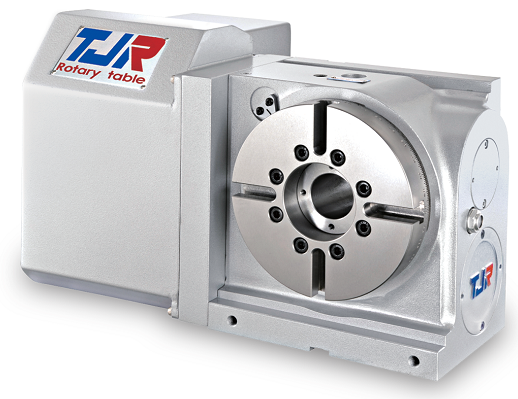
TJR’s AR Series left-hand motor mount rotary table brings the same proven AR Series performance to machines where left-side motor positioning is required by the work envelope or tooling layout. Face plate diameters range from 125mm (4.92″) to 250mm (9.84″).
The left mount configuration supports either full 4th axis operation integrated into the CNC machine control, or indexed positioning through TJR’s SAC (Single Axis Controller). Units can be oriented in both vertical and horizontal mounting positions, and right-hand and rear (back) motor configurations are also available — each equipped with a pneumatic braking system for reliable holding force under cutting loads.
Underpinning all AR Series tables is a radial-axial preloaded bearing system that provides the rigidity required for light and heavy cutting alike. The dual lead worm shaft and worm gear maintain precise, repeatable indexing accuracy in both directions over the long term.
Specifications
| Item / Model |
Unit
|
AR-125L
Request a Quote
|
AR-170L
Request a Quote
|
AR-210L
Request a Quote
|
AR-250L
Request a Quote
|
|---|---|---|---|---|---|
|
Table Diameter |
mm |
Ø 125 |
Ø 170 |
Ø 210 |
Ø255 |
|
Diameter of Table Central Hole |
mm |
Ø 35H7 |
Ø 67 |
Ø 67 |
Ø 67 |
|
Inner Diameter of Mandrel Sleeve |
mm |
– |
Ø 40H7 |
Ø 40H7 |
Ø80H7 |
|
Diameter of Center Through Hole |
mm |
Ø 25 |
Ø 40 |
Ø 40 |
Ø 40 |
|
Center Height (Vertical) |
mm |
110 |
135 |
160 |
160 |
|
Table Height (Horizontal) |
mm |
152 |
152 |
152 |
160 |
|
Table T-slot Width |
mm |
12H7 |
12H7 |
12H7 |
12H7 |
|
Guide Block Width |
mm |
14h7 |
18h7 |
18h7 |
18h7 |
|
Min. Increment |
deg. |
0.001 |
0.001 |
0.001 |
0.001 |
|
Indexing Precision |
sec. |
40 |
20 |
20 |
20 |
|
Repeatability |
sec. |
4 |
4 |
4 |
4 |
|
Clamping System (Pneumatic) |
kg/cm2 |
6 |
6 |
6 |
6 |
|
Clamping Torque |
kg-m |
13 |
31 |
31 |
31 |
|
Servo Motor Model (FANUC) |
Taper shaft |
α2i / ß4is |
α4i / α8i / ß8is |
α4i / α8i / ß8is |
α4i / α8i / β8is |
|
Servo Motor Model (MITSUBISHI) |
Taper shaft |
HF-75 / 105 |
HF-54 / 104 |
HF-54 / 104 |
HF-104 / 154 |
|
Speed Reduction Ratio |
– |
1:60 |
1:90 |
1:90 |
1:90 |
|
Max. Rotation Rate of Table (Calculate with Fanuc α Motor) |
r.p.m |
83.3 |
44.4 |
44.4 |
44.4 |
|
Allowable Inertia Load Capacity (Horizontal) |
kg.cm.sec2 |
2 |
5.4 |
8.3 |
11.7 |
|
Allowable Workpiece Load (Vertical) |
kg |
50 |
75 |
75 |
75 |
|
Allowable Workpiece Load (with Tailstock) |
kg |
100 |
150 |
150 |
150 |
|
Allowable Workpiece Load (Horizontal) |
kg |
100 |
150 |
150 |
150 |
|
Allowable Load with Rotary Table Clamping (F) |
kgf |
1000 |
1450 |
1450 |
1450 |
|
Allowable Load with Rotary Table Clamping (FxL) |
kgf.m |
45 |
100 |
100 |
100 |
|
Allowable Load with Rotary Table Clamping (FxL) |
kgf.m |
13 |
31 |
31 |
31 |
|
Strength of worm gears (Rotary axis)  |
kg.m |
9 |
18 |
18 |
18 |
|
Net Weight (servo motor excluded) |
kg |
34 |
50 |
55 |
58 |