TJR FAR Cradle Type – pneumatic brake tilt cradle type dual arm rotary table
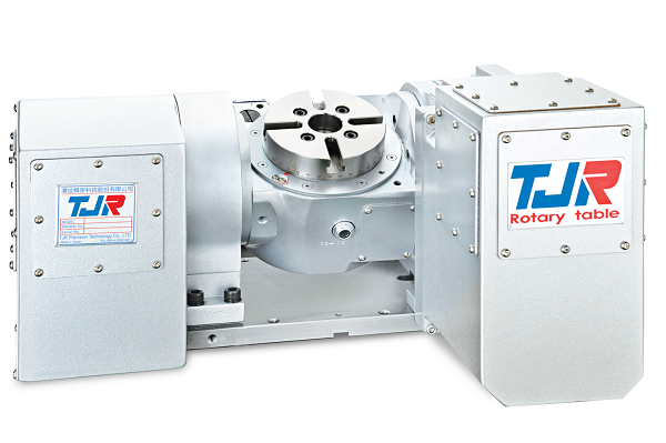
TJR’s FAR-Series cradle type rotary table features a dual arm design that provides enhanced support and stability compared to the single arm configuration. Available in sizes ranging from 125mm (4.92″) to 210mm (8.26″) face plate diameter.
The cradle design makes it well-suited for heavier workpieces that benefit from the additional rigidity of dual arm support, while still delivering the same 5-axis capability the FAR-Series is known for — adding true rotating and tilting axes to a standard 3-axis milling machine at a fraction of the cost of a dedicated 5 axis machine.
Full integration into your existing CNC machine control is supported for simultaneous 5-axis work, and the unit can also be connected to TJR’s DAC (Dual Axis Controller) for use across multiple machine tools when needed.
Like all FAR-Series tables, the cradle type is built around a large-diameter radial-axial preloaded bearing system for the rigidity required in both light and heavy cutting applications.
Specifications
| Item / Model |
Unit
|
FAR-125/125B
Request a Quote
|
FAR-170A (compact type)
Request a Quote
|
FAR-170 (Standard type) / FAR-170B (Back side motor type)
Request a Quote
|
FAR-210 (Standard type)
Request a Quote
|
FAR-210B (Back side motor type)
Request a Quote
|
FAR-210L (Extended cradle type)
Request a Quote
|
|---|---|---|---|---|---|---|---|
|
Table Diameter |
mm |
Ø 125 |
Ø 170 |
Ø 170 |
Ø 210 |
Ø 210 |
Ø 210 |
|
Diameter of Table Central Hole |
mm |
Ø 35H7 |
Ø 67 |
Ø 67 |
Ø 67 |
Ø 67 |
Ø 67 |
|
Inner Diameter of Mandrel Sleeve |
mm |
– |
Ø 40H7 |
Ø 40H7 |
Ø 40H7 |
Ø 40H7 |
Ø 40H7 |
|
Diameter of Center Through Hole |
mm |
Ø 25 |
Ø 40 |
Ø 40 |
Ø 40 |
Ø 40 |
Ø 40 |
|
Table Height (Horizontal) |
mm |
215 |
245 |
270 |
270 |
270 |
270 |
|
Table T-slot Width |
mm |
12H7 |
12H7 |
12H7 |
12H7 |
12H7 |
12H7 |
|
Guide Block Width |
mm |
14h7 |
18h7 |
18h7 |
18h7 |
18h7 |
18h7 |
|
Axis (Rotation) |
|||||||
|
Min. Increment |
deg. |
0.001 |
0.001 |
0.001 |
0.001 |
0.001 |
0.001 |
|
Indexing Precision |
sec. |
40 |
20 |
20 |
20 |
20 |
50 |
|
Repeatability |
sec. |
4 |
4 |
4 |
4 |
4 |
8 |
|
Clamping System (Pneumatic) |
kg/cm2 |
5 |
6 |
6 |
6 |
6 |
6 / Hyd.25 (optional) |
|
Clamping Torque |
kg-m |
13 |
31 |
31 |
31 |
31 |
31 / Hyd.35 |
|
Servo Motor Model (FANUC) |
Taper/Straight shaft |
α2i / ß4is |
α2i / α4is / ß4is |
α4i / ß8is |
α4i / ß8is |
α4i / ß8is |
α8i / α12is / ß12is |
|
Servo Motor Model (MITSUBISHI) |
Taper shaft |
HF-75 / 105 |
HF-75 / 105 |
HF-54 / 104 |
HF-54/104 |
HF-54/104 |
HF-104 |
|
Speed Reduction Ratio |
– |
1:60 |
1:72 |
1:90 |
1:90 |
1:90 |
1:90 |
|
Max. Rotation Rate of Table (Calculate with Fanuc α Motor) |
r.p.m |
83.3 |
41.6 |
44.4 |
44.4 |
44.4 |
44.4 |
|
Axis (Tilt) |
deg. |
-30º ~ +120º |
±100º |
±100º |
±100º |
±100º |
±100º |
|
Min. Increment |
deg. |
0.001 |
0.001 |
0.001 |
0.001 |
0.001 |
0.001 |
|
Indexing Precision |
sec. |
50 |
50 |
50 |
50 |
50 |
50 |
|
Repeatability |
sec. |
8 |
8 |
8 |
8 |
8 |
8 |
|
Clamping System (Pneumatic) |
kg/cm2 |
6 |
6 |
6 |
6 / Hyd.25 (optional) |
6 / Hyd.25 (optional) |
6 / Hyd.25 (optional) |
|
Clamping Torque |
kg-m |
31 |
31 |
31 |
31 / Hyd.35 |
31 / Hyd.35 |
31 / Hyd.35 |
|
Servo Motor Model (FANUC) |
Taper/Straight shaft |
α4i / ß8is |
α4i / ß8is |
α8i / α12is / ß12is |
α8i / α12is / ß12is |
α8i / α12is / ß12is |
α8i / α12is / ß12is |
|
Servo Motor Model (MITSUBISHI) |
Taper shaft |
HF-54 / 104 |
HF-54 / 104 (Straight shaft is not available) |
HF-104 |
HF-104 |
HF-104 |
HF-104 |
|
Speed Reduction Ratio |
– |
1:90 |
1:120 |
1:90 |
1:90 |
1:90 |
1:90 |
|
Max. Rotation Rate of Table (Calculate with Fanuc α Motor) |
r.p.m |
44.4 |
25 |
44.4 |
44.4 |
44.4 |
44.4 |
|
Allowable Inertia Load Capacity (Horizontal) |
kg.cm.sec2 |
0.97 |
2.2 |
4.13 |
41.3 |
41.3 |
41.3 |
|
Allowable Workpiece Load (0º Horizontal) |
kg |
50 |
60 |
75 |
75 |
75 |
75 |
|
Allowable Workpiece Load (0º~90º Tilt) |
kg |
35 |
40 |
50 |
50 |
50 |
50 |
|
Allowable Load with Rotary Table Clamping (F) |
kgf |
400 |
600 |
750 |
750 |
750 |
750 |
|
Allowable Load with Rotary Table Clamping (FxL) |
kgf.m |
31 |
31 |
31 |
Pne.31 / Hyd.35 |
Pne.31 / Hyd.35 |
Pne.31 / Hyd.35 |
|
Allowable Load with Rotary Table Clamping (FxL) |
kgf.m |
13 |
31 |
31 |
31 |
31 |
31 |
|
Strength of worm gears (Rotary axis)  |
kg.m |
9 |
18 |
18 |
18 |
18 |
18 |
|
Net Weight (servo motor excluded) |
kg |
97 |
125 |
160 |
153 |
163 |
156 |