Nexturn SA(XII) Series 8-Axis CNC Swiss-Type Lathes with Optional B-Axis
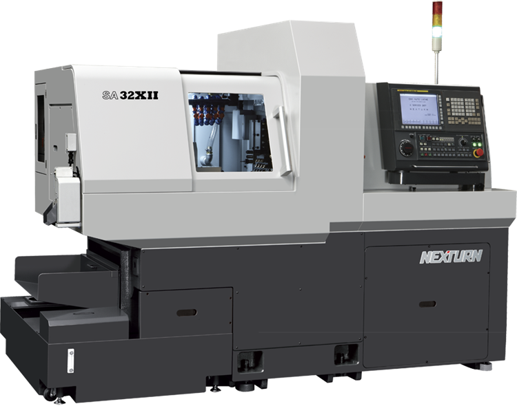
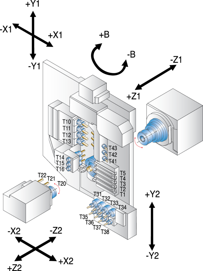
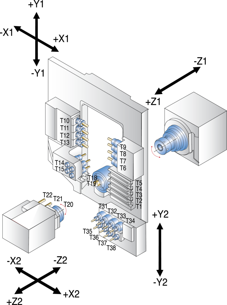
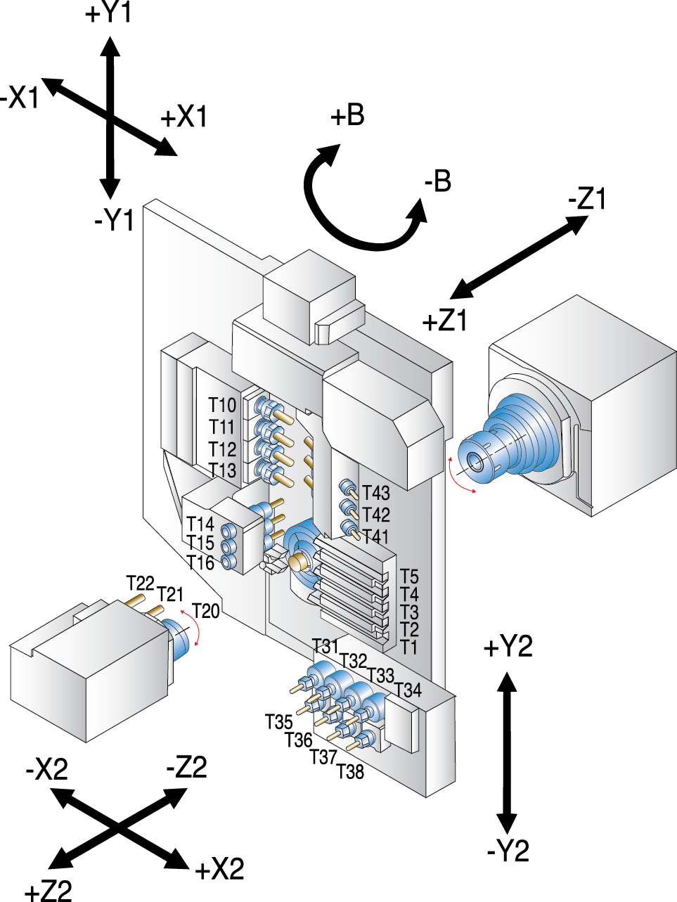
The Nexturn SA(XII) Series Swiss lathes — available in models SA-20XII (20 mm / 0.787”), SA-32XII (32 mm / 1.26”), and SA-51XII (51 mm / 2.00”) — delivers exceptional precision, rigidity, and performance for complex small-part production. Each machine is built for high-accuracy multitasking with 8 axes and an optional fully programmable 135° B-axis on the 20 mm and 32 mm models, providing 0°–135° of rotation for angled drilling, milling, and contouring.
With bar capacities from 20 to 51 mm and tooling configurations up to 33 tools, the SA(XII) line efficiently handles everything from intricate medical components to heavy-duty automotive and aerospace parts. Manufacturers in medical, aerospace & defense, automotive, electronics, and general precision turning industries rely on Nexturn for its unmatched combination of stability, accuracy, and ease of operation.
Competing directly with Marubeni Citizen-Cincom, Star, Mazak, Doosan, Tornos, Swiss-Tech, Swissturn, and Hanwha, Nexturn machines deliver cost-effective engineered solutions backed by Absolute Machine Tools’ automation and applications expertise.
Key Features
Specifications
| Item / Model |
SA-20XII
Request a Quote
|
SA-32XII
Request a Quote
|
SA-51XII
Request a Quote
|
|---|---|---|---|
|
FREE TRACER 20 Bar Feeder |
FREE TRACER 32V Bar Feeder |
FREE TRACER 51V Bar Feeder |
|
|
Number of Axes |
8 / 9 (opt.) |
8 / 9 (opt.) |
8 / 9 (opt.) |
|
Number of Channels |
2 |
2 |
2 |
|
Bar Capacity (Front/Rear) |
20 mm / 20 mm |
32 mm / 32 mm |
51 mm / 51 mm |
|
Max. Turn Length |
11″ |
11″ |
5.9″ |
|
Guide Bushing Type |
Synchronous |
Synchronous |
None |
|
Main Spindle |
5 HP / 10,000 RPM |
10 HP / 8,000 RPM |
17.5 HP / 6,000 RPM |
|
Sub Spindle |
3 HP / 8,000 RPM |
3 HP / 8,000 RPM |
20 HP / 6,000 RPM |
|
Total Tools |
31 / 29 |
31 / 29 |
22 |
|
Fixed Tools (Front/Rear) |
11 / 4 |
11 / 4 |
10 / 3 |
|
Live Tools (Front/Rear) |
12 / 10 |
12 / 10 |
6 |
|
Live Tools (Rear) |
4 |
4 |
3 |
|
Cross Live Tools |
1.3 HP / 6,000 RPM |
1.3 HP / 6,000 RPM |
3 HP / 6,000 RPM |
|
Backend Live Tools |
1.3 HP / 6,000 RPM |
1.3 HP / 6,000 RPM |
1.3 HP / 6,000 RPM |
|
B Axis |
0 – 135º |
0 – 135º |
0 – 135º |
|
C Axis Contouring |
Main/Sub |
Main/Sub |
Main/Sub |
|
CNC Control |
FANUC 31iT |
FANUC 31iT |
FANUC 31iT |
|
Weight |
7,920 lbs. |
8,140 lbs. |
9,240 lbs. |
Benefits for Metal Cutting Manufacturers
Together, these features allow manufacturers to produce tight-tolerance parts with superior surface finishes, reduced setup times, and greater profitability in competitive production environments.