APEC CM3040 – Aerospace Composite Machining Center
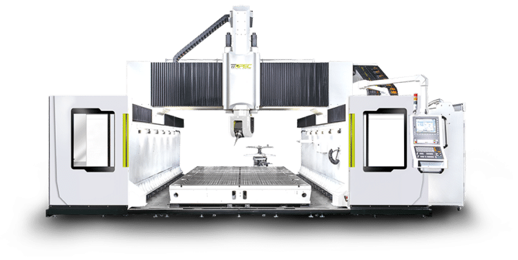
The APEC CM3040 is a 5-axis gantry machining center engineered specifically for aerospace composite processing and processing. Designed for the precision demands of carbon fiber, honeycomb core, and hybrid composite structures, the CM3040 ensures exceptional rigidity, accuracy, and environmental control for the world’s most advanced aircraft programs. Competing with Matsuura, CMI, and Belotti, the CM-3040 delivers the high-performance machining capability required to produce structural components that must be both lightweight and incredibly strong.
Benefits for Metal Cutting Manufacturers
For aerospace component manufacturers, the CM-3040 provides the perfect balance of stability, speed, and dust management when trimming, drilling, and finishing advanced composites. Its U-shape force flow casting structure and linear motor technology ensure vibration-free machining, while integrated dust collection systems maintain spindle health, operator safety, and part cleanliness. Manufacturers benefit from reduced cycle times, repeatable high-quality finishes, and consistent dimensional accuracy, ensuring their end-customers receive flight-critical components that meet the highest standards.
Key benefits include:
Key Features
Ideal Cutting Applications
Specifications
| Item / Model |
CM3040
Request a Quote
|
|---|---|
|
X-Axis |
157.48″ |
|
Y-Axis |
118.11″ |
|
Z-Axis |
59.05″ |
|
Rapid Traverse |
XY=118.10″ Z=787.40″/min |
|
Spindle Taper |
HSK-63F |
|
Spindle Speed |
28,000 RPM |
|
Spindle Power (S1/S6) |
20/25 kW |
|
Spindle Torque (S1/S6) |
23.6 ft. lbs. / 29.5 ft. lbs. |
|
Recommended 2-Axis Head |
Mono Support Milling Head |
|
Swivel/Rotation Torque |
A=98.1 ft. lbs./210.94 ft. lbs. |
|
Swivel/Rotation Speed |
A=C=100 RPM (Continuous) |
|
Swivel/Rotation Angle |
A = ±110° to ±125° |
|
Tool Shank |
20T pieces |
|
Max Tool Length |
11.81″ |
|
Max Tool Diameter with Adjacent Tool |
Ø2.76″ |
|
Weight |
130,000 lbs. |