You’ve Got EDM Questions? We’ve Got Answers!
I have a job that requires me to do a taper and I have not been successful at it in the past. I’m trying to cut a radius on the face of a round part at a 1.5 degree angle.
Let me just start by saying that as simple as Wire EDM can be it can also get very complex when it comes to bending a straight cutting tool around two fixed points through an infinite number of geometric elements using as many as seven axes. So for this forum, here is the basic machine preparation procedure and the program format for relatively common applications.
Assuming the machine is in good working condition, maintained, and a “Home Search” has been performed, here is the procedure to set the Z Axis position, vertically align the wire, and calibrate the wire guide positions in the Z axis.
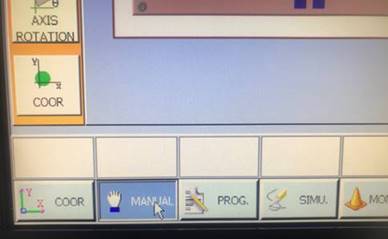
1. Select the Manual Button

2. Home Search

3. Calibrate the Z Axis Position (touch off on a standard)

4. Enter the height of the standard and click “Update Z-axis height”

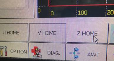
5. Home Search > Z HOME


Now you are ready to vertically align and calculate guide positions.
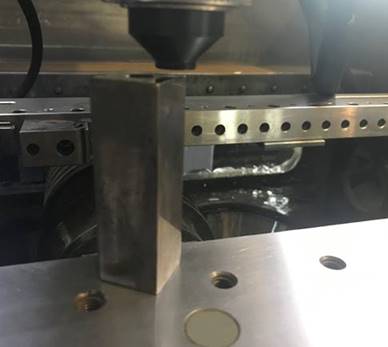
Set up the vertical alignment jig on the work table, position the Z Axis to 2.5” height.
6. Click Vertical

7. Auto vert. with alignment jig

8. AOTOVER. START

9. Click UPDATE DA/DB (Z4/Z4)

At this point the machine is prepped and ready to cut accurate taper angles. If you need help with specific taper cutting applications please contact Mark Cicchetti, EDM Technical Director at Absolute Machine Tools at (800) 852-7825 or https://absolutemachine.com/support/applications-training/.
This Q&A was featured in the Spring 2019 edition of EDM Today magazine.
We are a Job Shop, how do I quote wire EDM work accurately when some jobs we quote are within 5% while others are way off?
As a former EDM Job Shop owner/operator, I know how important it can be to quote jobs accurately. Not only does it determine the price of the work to be performed, it can also be a very useful tool for knowing your costs, scheduling the work through the shop, continuous improvement and ultimately increasing profitability.
Most Wire EDM manufactures provide some sort of cutting speed data along with their cutting condition documentation or run time estimate function on the control. Personally I found it more efficient to use the information provided with the documentation for quoting; using the control function means that the job must be completely programmed in order to get the estimate.
However there are variables that might exist in different applications which can cause raw cutting speed data to seem inaccurate. Because most or all wire EDM machines use some sort of servo control to maintain the desired spark gap, variables such as flushing, part shape and internal stress relief can dramatically effect cutting speed of both rough cut and subsequent skim cuts.
Here is one example that will hopefully serve as a guide for consideration in the quoting process.
Below is an example from the technology database for the AccuteX wire EDM showing the Total Process Feed-rate (TPF) and the results that will be achieved.

Notice there are 2 different rows showing TPF, one with the Corner and Arc Control off and one with the COR/ARC Control turned on. The COR/ARC control improves corner radii and sharp corner accuracy by adjusting power, servo settings, and flushing dynamically during machining. For our purposes we will use the TPF with the function turned off.
Example 1:
Circle 0.01” Dia. Wire 2 Cuts
Cut Length = 5.769
TPF 2 Cut = 1.42
Formula 5.769 / 1.42 = 4.06 hours total cut time

Example 2:
Gear 0.01” Dia. Wire 2 Cut
Cut Length = 5.769
TPF 2 Cut = 1.42
Formula 5.769 / 1.11= 5.20 hours total cut time

So if the material type, wire diameter/type, flushing, number passes, and the cut length are the same, why is the total cut time 28% longer for the gear than it is for the circle? The answer is in the shape being machined. Due to the wire drag during rough cutting there will be more stock left at each small internal corner of the gear as opposed to the larger radius of the circle. As a result the servo control of the wire machine will cause the linear feed-rate to drop significantly in order to remove that stock.
This begs the next question, where can the adjusted TPF be found that was used to calculate these types of applications? In this case the difference between the TPF with corner control off versus the TPF with corner control on is the answer.
Here is the formula based on the chart above;
1.49 / 2.11 = 0.72 or 28%, 4.06 hours X 1.28 = 5.196 total hours
Of course this is only one example of how different applications can make good data seem inaccurate. There is no substitute for experience. Maintaining and developing a substantial database of your own can be worth its weight in gold.
It is always a good idea to contact your OEM or support group to pick their brain and their database when venturing into new territory or help understanding the information provided.
AccuteX Service and Support can be contacted at service@absolutemachine.com or (513) 701-5550.
This Q&A was featured in the Winter 2018 edition of EDM Today magazine.
Can I get the Accutex to automatically reverse out of the cut along the program path without having to rewrite the path in reverse?
Yes, using the M70 (Start Point Retrace) Function. In cases where it would be beneficial to retrace out of the program path rather than cut the wire and position to the next point, the M70 function can reduce programming and provide safe retracing back to the start point. In the example shown below, the slot will be machined holding on to the slug for removal later.
In the case of a single cut or an odd number of cuts, the wire will end up inside the part. Inserting the M70 and preparatory codes, lines N30 through N32 in the below program example, the machine automatically retraces back through the path to the previous G92 thread point. This is done with no power or selectable power and applies the wire compensation offset of the previous path. The feed rate can also be set as shown in N30 M91 F12.0. It is possible to set the feed rate as high as 1 meter per minute (39.37 IPM) during the retrace, however, it might be a good idea to consider the intricacy of the path and tight cornering that might catch the wire on the way out.

This Q&A was featured in the Summer 2018 edition of EDM Today magazine.
We frequently run into situations where we have to choose to either drop slogs as we go on our multi-opening blocks or hold on to slugs for untended operation. What is the best way to handle the programming for the different situations?
The easiest way to handle this on any Accutex is to use the advanced AWT functions found on the AWT Setting Screen. Here are the instructions to explain the operation for dropping or holding slugs and skim cutting.
AWT Type on AWT Screen is used for creating a program using M20, M21 & M22 placed in the program in such a way as to allow the operator to create a program with these commands that the operator need only to change the AWT Type to hold the slug or part during the rough and/or finish cuts, and to cut off the slug/part and run the program again.
AWT must be turned ON, on the AWT Screen.
Parameter 107=OFF: Controller will skip geometry after wire cut (M21, M22, M23) and move DIRECTLY to next Wire thread (M20, M21), depending on setting of AWT TYPE.
Parameter 107=ON: Controller will Dry Run remaining geometry after wire cut (M21, M22, M23) until it reaches the next Wire thread (M20, M21), depending on setting of AWT TYPE.
AWT TYPE description (This description is for Mitsubishi format syntax, parameter 629 set to “0”. For Fanuc format, M20=M60, M21=M50, M22=M61 & M23=M62 in the instructions below)
Type 1 (M20/M21): This is normal AWT operation for Auto Wire Thread and Auto Wire Cut. M20 commands the machine to insert or thread the wire and M21 commands the machine to cut the wire. When using the AWT TYPE for slug retention M20 will be used at the beginning of the program to thread the wire, M21 will be placed in the geometry path before the slug cut-off to cut the wire, and allow the remaining geometry to be skipped or executed in Dry Run mode, depending upon whether Parameter 107 is turned on or off.
Type 2 (M21/M22): The controller will find the first M20 and jump to the next M21 to thread the wire. After threading, the program will be executed normally until it reaches the M22 (wire Cut) command. The controller then skips the geometry following M22 until it reaches the next M21. If there is not another M21 in the code, the machine executes to the end of the program.
Type 3 (M20/M23): The controller will jump to the first M20 and thread the wire, then execute the program normally until it reaches the next M23 to cut the wire. After completion of the wire cut, the controller skips the remaining geometry until it reaches the next M20. If there are no more M20’s the program executes to the end of the program.
This Q&A was featured in the Spring 2018 edition of EDM Today magazine.
Can I start my program somewhere in the middle with skims and bypass all the first cuts? Also, how do I set the E-Cond and Wire Offsets if the header in the program gets bypassed?
All the AccuteX wire EDM machines have a function called N-CODE SET which is found on the Monitor Screen. For AU, EZ and SP models there is a 3 step process.
- First, use the S.PT button on the remote to return back to the program start point.
- Next, find the sequence number where you would like to begin, usually it’s the line after the M20/ M60 AWT command. Go to the Command Line (Fig. 1) and type M (move to) N (sequence number) followed by the sequence number. Example; MN312 for the program (Fig. 2) and press enter. The machine will move directly to the Thread Point or Start Point for that operation.
- Last, from the Monitor Screen press the N-CODE SET (Fig. 3) and type the same number 312 (Fig. 4) and press enter. The control will begin quickly reading from the top, setting all the E-Cond, Wire Offset registers and any other user variables in the program. Use the AWT button to thread the wire if necessary and press CYCLE START from the remote and you are off and running.
AccuteX has simplified the function on the newer models, AL, GE and AU to incorporate all the steps into one function.
- From the Monitor Screen select N-CODE SET (Fig. 3) and type the desired sequence number. Highlight the SET N Code and Move option and click OK. Click the USE MEMORIZED (1ST START POINT) (Fig. 5).
Same as before the control will begin quickly reading from the top, setting all the E-Cond, Wire Offset registers (Fig. 6) and any other user variables in the program; then rapid directly to the proper location. Use the AWT button to thread the wire if necessary and press CYCLE START from the remote. You are now off and running!
This Q&A was featured in the Fall 2017 edition of EDM Today magazine.
How do I choose the right EDM Drill tube for our different applications?
I will try to make this short and sweet by offering the basic principals. I am sure there will be many variables that end users experience and to their credit find solutions that the “experts” would find surprising.
First there are several different configurations and materials available.
The basic materials are copper and brass, these make up 95% or more of the tube sales. Copper tubes work best in carbide and brass for steel and almost anything else.
The other significant option relates to the number of channels through the tube used for flushing. The most common are single, double and triple channel although I have seen more than three holes in larger diameter tubes but the function is basically the same. Again, we are sticking to the basics here and the information will be most relevant for the typical size range of 0.3mm to 3.0mm diameter applications.
Single channel tubes typically burn faster than any other type due to the fact that they machine less material than multi channel tubes. Except for a big problem that can be summed up in one word:
sta·lag·mite
stəˈlaɡˌmīt/
noun
- a mound or tapering column rising from the floor of a cave, formed of calcium salts deposited by dripping water and often uniting with a stalactite.
Google Dictionary
The definition is good except of course that they are not formed by dripping water over a long period of time and there is never a stalactite associated with it. It is in fact formed in seconds by the the material left behind from the rotating electrode with a single hole right on the center. The over burn from the spark gap is not large enough to erode away the center material in electrodes larger than just 1mm in diameter. These stalagmites when drilling deeper holes grow up into the center of the electrode and eventually break off and cause shorting and inconsistent drilling. It will be flying along along then suddenly just start sputtering and backing up for no good reason, but there is. That’s why multi-channel tubes were made. The rotating electrode with multiple offset channels erode all the material in the hole making it possible to do deep hole drilling without shorting or backing up.
Here are the basic applications:
Single Channel Tubes: 0.7mm diameter or for through holes in materials less than 10mm in thickness. Never use a single channel tube in blind holes, those stalagmites will get you every time.
Double channel or “I Bar” or “Double D” tubes are available but I have had mixed results based on the manufacturing method of the tubes. In many cases the tubes are made by drawing a round tube around a rectangular bar. I have actually seen the center bar separate from the tube in deeper holes. You can imagine the problems this can cause.
When possible, the three channel precision extruded tubes offer the most consistent results in most common applications. The limitations for availability of these tubes is primarily based on the outside diameter of the tube. It is hard enough getting a hole in the center of a 0.1mm tube let alone multiple as you can imagine.
This Q&A was featured in the Summer 2017 edition of EDM Today magazine.

